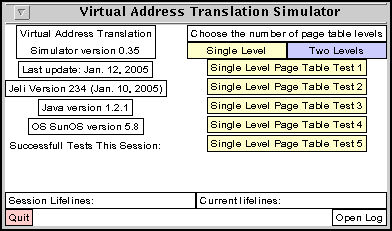
Figure 1: The main simulator window.
The Address Translation Simulator is a Java application that can be used for exploring aspects of address translation. It supports 1 and 2-level page tables and a translation lookaside buffer. The simulator gives the user a logical address and information about the memory system, such as the number of bits in logical and physical address and the page size. The user then must determine the corresponding physical address or if a page fault occurs.
The simulator can be used for learning or testing. In the learning modes, various levels of help are available. The steps necessary to translate the address can be shown, hints are available for each step and individual steps can be done automatically, if the student gets stuck.
In the testing modes, the simulator keeps track of what the student does and records this information in a log file. The amount of detail kept in the log file can be adjusted, from just keeping count of what was completed successfully to logging each action of the user. The simulator can mail the log file to the instructor when the student has completed an assignment.
System requirements:
User requirements:
Running in a non-Windows environment:
If you installed the simulator by copying the files from a CD, the
scripts may not have the correct permissions to run. The convert
and runaddress files should be executable.
The ASCII files distributed with this distribution are in the Windows format
in which lines end in a carriage return followed by a line feed.
It may be more convenient to have the carriage returns removed.
If you are running under UNIX, Linux, or Mac OSX, it
may be more convenient to have the carriage returns removed.
You can remove all of the carriage returns from these files by executing the
convert script.
If you do a custom installation, you can put the jar files anywhere you want. Modify the runaddress.bat (Windows) or runaddress (Unix, Linux, Mac OSX) file so that the JARDIR1 or JARDIR2 variables points to the location of the jar files.
If the simulator does not start, make sure you have the Java runtime executables
in your path. In a command window, execute:
java -version
and make sure this displays a version later than 1.0.

Figure 1: The main simulator window.
Figure 2 shows the result of pushing one of the yellow single level page table test buttons.
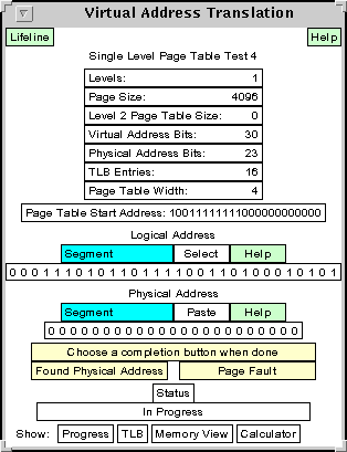
Figure 2: A single level page table test.
At the top of this window are green Lifeline and Help buttons that can give guidance in using the simulator. Most windows used by the simulator have a green Help button that pops up a message about using the window. In this case the message is shown in Figure 3. These Help windows stay visible for only a short time unless you click the button on the bottom of the window.
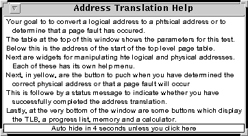
Figure 3: The Help message for a single level page table test.
The simulator window contains the data for doing an address translation problem. Seven values are given:
Next appear two widgets containing the logical and physical addresses. The value of the logical address is given (in binary) and the value of the physical address is to be determined by the user.
Basically, the fields of the logical address are manipulated to produce the fields of the physical address. The widgets are designed for easy manipulation of these bit fields as explained below..
Below the logical and physical address widgets are two yellow buttons used to indicate when the user is done generating the physical address. Push the Found Physical Address button when you think you have correctly filled in the physical address or the Page Fault is you determined that a page fault has occurred.
The Status field below this indicates whether the test was done successfully or not. It indicates In Progress until one of the above buttons is pushed, and then indicates success or failure.
Lastly are a row of buttons for displaying information useful in calculating the physical address. These include displays of the TLB and memory (mainly in the form of page tables), a progress list to guide the user through the steps needed to do a translation, and a binary bitfield calculator for adding and shifting binary values.
The general paradigm for manipulating the binary bit fields is cut and paste, or more precisely, copy and paste since bit fields are never removed (cut), just copied. The simulator uses a single clipboard shared by all entities used by the simulator. Bit fields are moved around by first selecting them by clicking the mouse appropriately. This puts the bit field in the clipboard and then pasting them in the desired place, again by appropriately clicking the mouse.
Some fields such as those of the logical address, TLB and memory cannot be changed and so can only be selected. Others, such as those in the physical address only be pasted into.
Each of the widgets has two rows of information. The top row is a set of buttons controlling the mode of the widget. The possible modes are Segment, Select, and Paste. The current mode is highlighted with a cyan background. In Figure 2, both widgets are in Segment mode. An additional Help button describes how to use the widget.
Since the contents of the logical address cannot be changed by the user, this widget does not have a Paste mode. The widget starts in the Segment mode that allows it to be divided into fields. For single level page tables, only two fields are allowed, the high order bits representing a page number and the low order bits representing the page offset. Click the mouse between two of the binary digits to segment the logical address. As you move the mouse in the logical address, the Segment button shows the sizes of the two fields that would be obtained by clicking the mouse at that time. Figure 4 shows the logical address widgets after the mouse has divided it into fields of size 18 and 12.

Figure 4: The logical address segmented into fields of size 18 and 12.

Figure 5: The logical address with the offset field selected.

Figure 6: The physical address after the offset has been pasted.
The progress list for the address translation problem shown in Figure 2 is given in Figure 7. The figure shows the state of the progress list after the offset has been correctly copied into the physical address as shown in Figure 6.
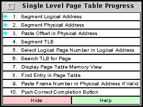
Figure 7: The progress list after the offset has been correctly copied into the physical address.
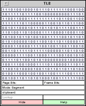
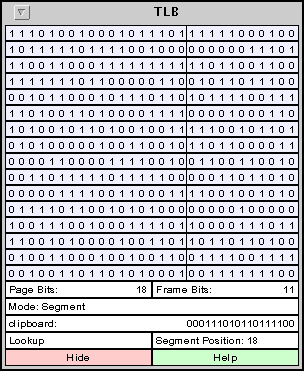
Once the TLB is segmented, the simplest way to do a lookup is the put the page number to be looked up in the clipboard and clicking the Lookup button in the TLB. If the Logical Address is in Select mode, as it would normally be from pasting the offset in the physical address, just click on the page number filed in the Logical Address. This puts in in the clipboard and this value will appear in the TLB clipboard entry. Push the Lookup button in the TLB. If the lookup is successful, the corresponding frame number will be highlighted and put in the clipboard. Once this is done, it can be pasted into the physical address simply by clicking on the frame number field of the physical address.
 |
 |
|
| a) | b) |
Figure 8: The TLB, before and after segmenting.
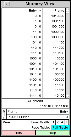
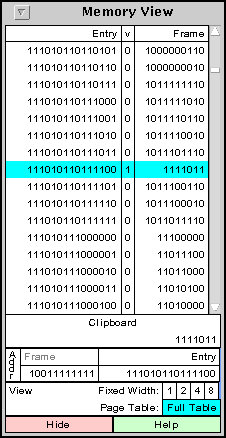
If the lookup in the TLB is not successful, a page table lookup is necessary. Display the page table by pushing the Memory View button as shown at the bottom of Figure 2. The default memory view shows the full single level page table, as seen in Figure 9a. The index of the entry appears (in binary) on the left followed by the valid bit and the frame number. Use the scroll bar to scroll through the page table. The starting frame number of the page table is automatically set and shown below the word Frame at the bottom of the window. Since the page table may be large, the simplest way to find an entry in the page table is to put its index in the clipboard and push the Entry button near the lower right side of the window. The correct value should still be in the clipboard from the TLB lookup. If not, select the page number from the logical address and then click the Entry button in the memory view. If the lookup is successful, the corresponding entry is highlighted and the frame number is put in the clipboard. The result of a successful lookup is shown in Figure 9b.
If the valid bit of this entry is clear, it indicates a page fault. Push the yellow Page Fault button as in Figure 2. Otherwise, the frame number must be pasted into the physical address. Assuming the Physical Address is still in Paste mode, just click the left field in the Physical Address. Now click the yellow Found Physical Address button. After pushing one of these yellow buttons, the Status will indicate success or failure. If you were successful, the test number will appear in the list of successfully completed tests in the menu window shown in Figure 1.
 |
 |
|
| a) | b) |
Figure 9: The Memory View, before and after a successful lookup.
The progress none option completely turns off the progress list so that it cannot be displayed.
If progress help is active, clicking on one of the steps in Figure 7 gives information about how to accomplish this step. Figure 10 shows the result of clicking on step 3.
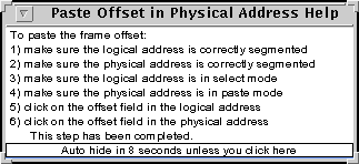
Figure 10: A help message for pasting the offset in the physical address.
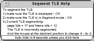
Figure 11 shows three possibilities for the result of clicking on step 4 in Figure 7. Figure 11a shows the case in which the TLB has not already been displayed. Clicking on line 2 in this figure displays the TLB and changes the message to the one in Figure 11b. The the TLB is displayed, but incorrectly segmented, the message would appear as in Figure 11c. In any of these, clicking on the last line will correctly segment the TLB.
 |
 |
 |
| a) | b) | c) |
Figure 11: A help message for pasting the offset in the physical address.
A lifeline is used when the user is stuck and does not know how to proceed. The Lifeline button provides help for the next step in the address translation. Figure 12 shows the lifeline displayed corresponding to the situation in Figure 7. The lifeline display always has a Perform Step that can be used to execute the next step in the address translation.
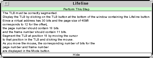
Figure 12: A lifeline.
Lifelines are meant to be used in testing mode while progress help is meant for practice mode. Lifelines can be limited while progress help is either available or not. The use of lifelines is always logged so the instructor can see exactly where and how many lifelines are used.
| Keyword | Values | Meaning |
| General Parameters | ||
| user | anything | The name of the current user. This appears in the log file. |
| quiet | none | Turns off all sounds generated by the simulator. |
| Help Parameters | ||
| lifelines | 2 integers | If given, these numbers are the number of lifelines per test and the total number of lifelines allowed. Zero values indicate no lifelines (the default). The value -1 can be used to indicate no limit to the number of lifelines. |
| progress | a string | The valid strings are none, help or do. By default, the Progress window is available but the help menus for each progress step are not available. The value none indicates that the Progress window is not available. The value help indicates that help is available for each progress step and the value do also allows do it lines for the current step. |
| Logging Parameters | ||
| log | a string | The valid strings are all, completion, and summary. See the section on Logging. |
| logfile | a filename | The name of the log file. The extension .html will be appended to this. The default log file is logfile.html. |
| logdir | a directory path | If given, this is the directory for storing the log file. If not given, the log file is stored in the current directory. |
| uniquefilename | an integer | If given, use a unique file name each time a log file is opened. Do this by appending an integer with the given number of digits to the filename. |
| port | an integer | If this value is greater than zero, remote logging will be used with this port. The default is 0. |
| Test Configuration | ||
| nosingleleveltests | none | Inhibits the default single level tests. |
| notwoleveltests | none | Inhibits the default two level tests. |
| singlelevelvalues | 4 integers | The default values for single level page table tests. |
| twolevelvalues | 5 integers | The default values for two level page table tests. |
| testfilename | a string | A file containing tests. |
| Email Configuration | ||
| a string | The valid strings are none, attempt, success and done. | |
| emailfrom | a string | The sender of the email. |
| emailto | a string | The receiver of the email. |
| emailhost | a string | The email server. |
Logging is controlled by the configuration keywords: log, logfile, logdir, uniquefilename and port.
The log configuration keyword determines how much information is logged. The default is all which causes all actions by the user to be logged. Information is only stored in the log file when a test has been successfully completed. Figure 13 shows the result of logging one test using this default.
| Test 3: 2: Single Level Page Table not in TLB | ||
| 1 | 7.437 | Logical Address Frame Selected: 110100010101 |
| 2 | 7.437 | Physical Address Paste Offset: 110100010101 |
| 3 | 7.687 | TLB segmented into 18 and 11 |
| 4 | 7.890 | Logical Address Page Selected: 000111010110111100 |
| 5 | 9.249 | Button Pushed: Progress |
| 6 | 12.577 | Progress Tracker Event: Progress Tracker Help for 6. Search TLB for Page |
| 7 | 15.280 | TLB lookup failed |
| 8 | 22.093 | Lifeline Requested: Paste Frame Number in Physical Address if Valid |
| 9 | 25.358 | Automatic Step Performed: Paste Frame Number in Physical Address if Valid |
| 10 | 25.358 | Physical Address Paste Frame: 00001111011 |
| 11 | 30.592 | Attempt Completion: Correct Physical Address Found |
| Lifeline count: 1 Automatic step count: 1 | ||
Figure 13: log file produced with the default of logging all actions.
The other two option only log the results of the tests and the log information is only updated when the log is closed or the Quit button is pushed. If log completion is specified, only those tests that have been successfully completed will be listed in the log file. Figure 14 shows an example of this. If log summary is specified, a count is given of the number of correct and incorrect attempts for each test attempted. This just counts the number of times the yellow completion buttons of Figure 2 have been pushed. An example is shown in Figure 15.
| The following tests were completed: |
| 2: Single Level Page Table not in TLB |
| 5: Single Level Page Table with Page Fault, no TLB |
| 3: Two Level Page Table with Page Fault |
| 4: Two Level Page Table with Illegal Page |
Figure 14: A log file produced with the log summary configuration.
| Test | Successes | Failures |
| 1: Single Level Page Table in TLB | 1 | 0 |
| 2: Single Level Page Table not in TLB | 1 | 3 |
| 3: Single Level Page Table with Page Fault | 1 | 0 |
| 5: Two Level Page Table without TLB | 1 | 0 |
| 7: Two Level Page Table with Illegal Page | 6 | 10 |
Figure 15: A log file produced with the log attempts configuration.
The log is stored in a file in HTML format so it can be displayed in a browser. The name of the file is given as the parameter to the logfile keyword. The extension .html is appended to this. The file is stored in the directory given by the logdir keyword.
By default, each time the log file is opened, the old log file is replaced. If the uniquefilename keyword is used, each time the log is opened a distinct filename is used. It is made by appending an integer to the filename given by the logfile keyword. The parameter to uniquefilename is the minimum number of digits used for this integer. The integer used is the smallest one (starting with 1) that has not already been used.
If the port keyword is given, the parameter is the port number to used for a remote connection to a logging server for storing the log file. This is only appropriate when the simulator is started as an applet from a browser.
For the two level tests using a TLB, TLB entries contain a full page number consisting of the top level and second level page numbers and a frame number.
Seven two level page table tests are built into the simulator. Three tests do not use the TLB at all and correspond to no page fault, a page fault, and an invalid reference. There are four tests using the TLB, these three plus a reference in which the full page number is in the TLB.
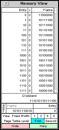
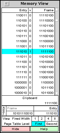
Figure 16 shows a typical two level page table test and Figure 17 shows the corresponding progress list. The TLB lookup for the two level page table is the same as for the single level page table and is exactly the same if the item is found in the TLB. If not, the top level page table must be searched. Figure 18a shows the top level page table gotten by clicking the Memory View button in Figure 18.
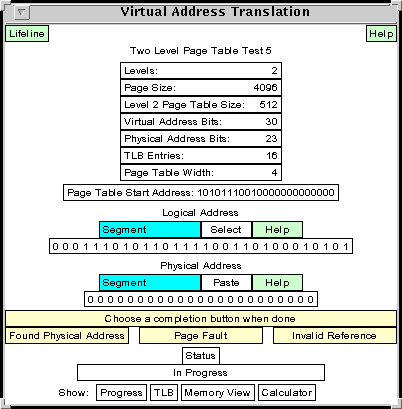
Figure 16: A two level page table test.

Figure 17: The progress list for a two level page table test.
 |
 |
|
| a) | b) |
To look up an entry in this page table, the top level page number must be found. Set the logical address to segment mode to segment the logical address again. Since the second level page number is 9 bits wide, the top level page number contains (30-12-9) = 9 bits. Click on the logical address to segment it into pieces with sizes 9, 9 and 12. Change the logical address to select mode and click on the top level page number. This puts the page number in the clipboard. Click on the Entry button in the memory view of Figure 18a to look find this entry in the top level page table. The entry is highlighted as in Figure 18b.
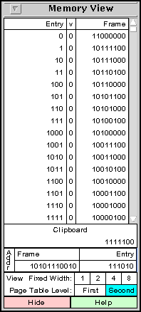
If the valid bit were clear, this would be an invalid memory reference. Push the Invalid Reference button in Figure 16 to complete the test. Since in this case the valid bit is set, the entry contains the frame number of the second level page table. This frame number has also been put in the clipboard. Push the Second button (next to the highlighted First button in the memory view of Figure 18b. This displays a second level page table shown in Figure 19a.
 |
 |
|
| a) | b) |
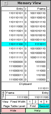
Click the Frame button to set the starting from number of this page table from the value in the clipboard. Now it is time to look up the second level page number in this table. Click on the second level page number field in the logical address of Figure 16 to put it in the clipboard. Then click the Entry button in the memory view of Figure 19a. The result is shown in Figure 19b. If the valid bit of the highlighted entry were 0, this would indicate a page fault. Click on the yellow Page Fault button in Figure 16 to complete the test.
Since the valid bit in this case is set, the frame number of the physical address is in this entry. It was also put in the clipboard. Click the frame number field in the physical address in Figure 16 to paste the frame number in the physical address. The physical address is now correctly set, so push the yellow Found Physical Address button to complete the test. The status should indicate that the correct physical address was found.
The singlelevelvalues keyword takes four integer parameters representing,
in order, the
number of TLB entries, the number of bits in the logical address, the number of
bits in the physical address and the number of bits in the page offset.
The twolevelvalues keyword takes five integer parameters
representing, in order, the number of TLB entries, the number of bits in the
logical address, the number of bits in the second level page number, the number
of bits in the physical address and the number of bits in the page offset.
The following two lines in the configuration file will set the default tests
to use a TLB with 8 entries, a logical addresses of 32 bits,
physical addresses of 26 bits and a page size of 1024 (210).
The two level page table tests will use 11 bits for the second level page
number.
singlelevelvalues 8 32 26 10
twolevelvalues 8 32 11 26 10
You can also inhibit either all of the default one level tests or two level tests with the configuration keywords nosingleleveltest or notwoleveltests.
It is also possible to completely replace the default tests with tests of your own design. Create a test configuration file and use its name as the parameter with the testfilename configuration keyword.
The format of this file is fairly rigid, and a single error will cause the entire file to be rejected by the simulator. If it is rejected, the simulator will tell you which entry was rejected.
Each test is described by two lines followed by 4 boolean values, 9 integer values and 1 boolean value. These last 14 values are in free format, that is, they can be separated by any white space or commas. The boolean values are given as either the string true or the string false. These are not case sensitive.
The file consists of an arbitrary number of these tests, one after the other.
The first two lines of a test specification give names to be used for the test. The first line is the name that is given to the user, referred to as the display name. This is the name that appears in the buttons on the right side of Figure 1 or as the heading in Figure 2. Typically it contains a test number but does not divulge what is being tested. An example might be Single Level Page Table Test 3. The second line is the name that will appear in the log file or email to the instructor. This should be more description of what is being tested. An example might be Single Level Page Table In TLB.
The rest of the values are described in the following table. Note that the mnemonics do not appear in the file and are just given for easy reference.
| mnemonic | type | meaning |
| useTlb | boolean | if true, a TLB is used. |
| inTlb | boolean | if true, the page number is in the TLB. |
| pageFault | boolean | if true, a page fault occurs |
| legalPage | boolean | if true, the first level lookup of a 2-level page table is successful. |
| tlbEntries | integer | the number of entries in the TLB |
| logicalAddressBits | integer | the number of bits in a logical address |
| logicalAddress2Bits | integer | for two level page tables, this is the number of bit in the second level page number. |
| physicalAddressBits | integer | the number of bits in a physical address |
| pageSizeBits | integer | the number of bits needed to represent an offset. The page size is 2 to this power. |
| logicalAddress | integer | the logical address. If the value given is negative, a random value will be chosen. |
| frameNumber | integer | the frame number of the translated address. If this value is negative, a random value will be chosen. |
| pageTableStartFrame | integer | The starting frame number of the page table. If this value is negative, a random value will be chosen. |
| pageTableEntryBytes | integer | the number of bytes in a page table entry. If this value is negative, page table entries will be the smallest power of two that will fit a frame number and valid bit. |
| byteOrderLittle | boolean | if true, little endian is used |
The values of legalPage and logicalAddress2Bits are ignored for single level page tables. Other values are modified if not consistent. For example, useTLB and inTLB are set false if the number of TLB entries is 0.
Below is a simple test configuration file with two test cases:
First Address Translation Test
Single level page table with page fault
true false true false
12 25 0 18 8
12345 35 1024 4
true
First 2 Level Test
Two level page table with full lookup necessary
true, false, false, true,
16, 30, 9, 23, 12, 123456789, 123,
54321, 4, true
In order to set up email, three additional parameters must be set in the configuration file. The parameter to emailfrom is the return email address of the sender. The parameter to emailto is the email address to which the mail is sent. Lastly, the parameter to emailhost is the name of the mail server that sends out mail.
The information in the email messages is sent in HTML format in the body of the message (not as an attachment). This should be able to be read with most mail reading programs. The content of the email messages is the same information that would appear in a log file. The amount of information is controlled by the log configuration keyword. Examples of the different amount of information that can be sent in an email message are shown in Figures 13, 14 and 15.
Using email with the simulator requires an additional Java packages which may not be part of the standard Java runtime distribution. Two jar files, mail.jar and activation.jar are included with this simulator for your use. If these do not work with your system, you will need to obtain another version of these files.